Design data
Below are listed the most important parameters that are required to properly design an MBR (Membrane Biological Reactor) system:
- Feed quantity:
- Average Daily Flow (ADF);
- Peak Hourly Flow (PHF);
- Feed quality:
- Non-ionic: Total Suspended Solids (TSS), Volatile Suspended Solids (VSS), 5-days Biological Oxygen Demand (BOD5), Chemical Oxygen Demand (COD), Organic Nitrogen, Total Phosphorous (TP), Fats, Oils and Greases (animal and vegetable as well as mineral);
- Ionic: Ammonium, Nitrates, Phosphates, Calcium, Alkalinity;
- Others: Temperature, pH;
- Other considerations: target effluent quality, redundancy, available footprint, existing facilities.
Of course, other parameters might be required, depending on the specific application.
Plant-wide design aspects
Pre-treatments
The following general pre-treatment guidelines must be followed:
- The influent wastewater must be mechanical pre-treated for elimination of coarse particles by using a suitable fine screen (mesh or punched hole);
- The influent wastewater should be pre-treated for elimination of grit (if necessary);
- Influent FOG concentrations must be lower than 100 ÷ 150 mg/L;
- Influent mineral oils and grease concentrations must be lower than 10 mg/L;
- Influent calcium concentrations must be lower than 200 mg/L;
- Influent wastewater pH and macro-nutrients concentrations should be corrected in order to ensure the development of a healthy activated sludge (if necessary);
- Influent toxic compounds shall be removed to ensure the development of a healthy activated sludge (if necessary).
Fine screening
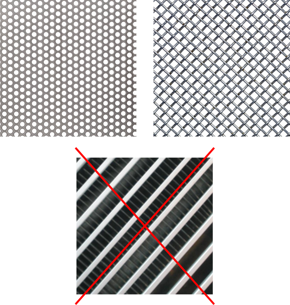
Focusing on fine screening as it one of the critical points in ensuring the successful operation of MBR systems, we recommend:
- 0.5 ÷ 2 mm aperture size (better, 0.5 ÷ 1 mm to reduce the accumulation of large particles with the bioreactors and to reduce the clogging potential of the mixed-liquor);
- Punched hole (top left) or mesh type (top right);
- Wedge wire (bottom) is not recommended;
- Any bypass is not allowed.
Depending on the size of the coarse solids present in the raw wastewater, a fine screen might be preceded by a coarse screen (6 ÷ 10 mm) in order to prevent too frequent backwashing of the fine screen.
Biological reactors
- Design methods and kinetic coefficients values are similar to the ones of CAS (Conventional Activated Sludge) systems;
- As well, the WAS (Waste Activated Sludge) production is like CAS systems having similar sludge age values;
- Typical biomass concentration values are equal to 6 ÷ 12 kg SS/m3 (in case of submerged systems) or 10 ÷ 40 kg SS/m3 (external systems). Obviously, this has an impact on the oxygen transfer, where the α-coefficient decreases with increasing biomass contents;
- The Sludge Retention Time (SRT) shall be higher than 8 ÷ 12 days and lower than 50 ÷ 60 days in order to improve the mixed-liquor filterability;
- Complete nitrification shall be achieved (if applicable), so that biodegradable organics have been removed and – thus – the corresponding fouling potential has been minimized;
- In case denitrification is required, provisions shall be made to minimize the recycled dissolved oxygen. For instance, a deoxygenation tank might be added or two separate recycle streams could be used;
- In case of submerged systems, the RAS (Return Activated Sludge) capacity shall be designed to avoid mixed-liquor suspended solids (MLSS) contents within the filtration tank higher than 15 ÷ 20 kg/m³ at all times.
As well, the following feed wastewater/mixed liquor limitations are to be considered:
| Parameter | Unit | Value |
| Water temperature | °C | 5 ÷ 37 |
| pH | – | 6.5 ÷ 8.0 |
| Sludge retention time (or sludge age) | d | 12 ÷ 60 |
| F/M ratio | kg COD/(kg SS·d) | 0.08 ÷ 0.30 |
| Mixed-liquor suspended solids concentration | kg SS/m3 | 6 ÷ 12 (submerged), 15 ÷ 40 (external) |
| Mixed-liquor time to filter | s | 50 ÷ 200 |
| Effluent ammonia nitrogen concentration | mg NH4+-N/L | < 1 |
| Dissolved oxygen | mg O2/L | > 1.5 |

How can we help you?
Do not hesitate to contact our experts who will work with you to conduct project assessments, run a pilot test, customise, design and install your membrane filtration system, which best fits your needs.
Membrane filtration unit
Based on the design data (both of the raw wastewater and of the biological reactor), we size the membrane filtration unit so that enough permeate is produced to meet the capacity requirements.
Depending on the type of membranes used, we distinguish two types of MBRs:
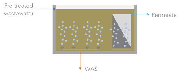
Submerged (or immersed) membranes inside:
- The biological reactor:
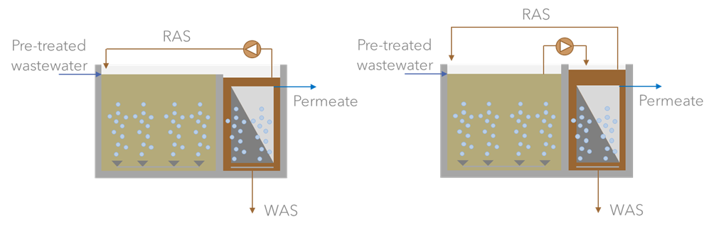
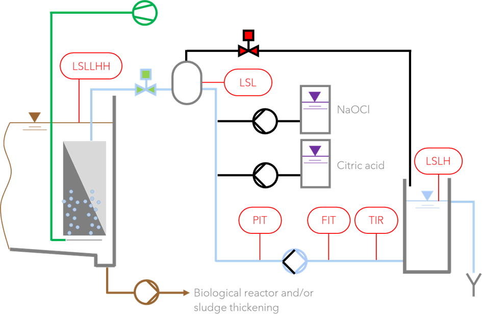
- A dedicated filtration tank with pump-from (left) or pump-to (right) configuration:
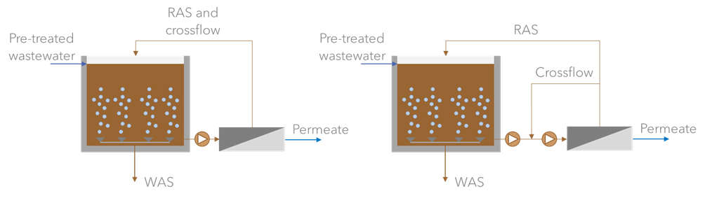
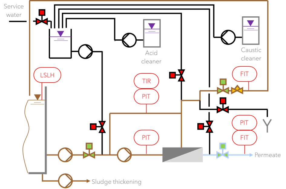
- External (or side-stream) membranes with pure crossflow (left) or feed-and-bleed (F&B, right) configuration:
Usually, submerged MBRs are used in medium to large installations because of the lower energy consumption while external (or sidestream) MBRs are used in small to medium installations because of the lower chemical consumptions and ease of installation and maintenance.
In particular, the sizing involves the following parameters:
- The duration of the phases of the filtration cycle, which include:
- Production;
- Relaxation;
- Backwash – typical of submerged systems only;
- Chemical cleaning interventions;
- Water flux, the extracted flowrate per unit of membrane area. In case of submerged membranes, two different production fluxes are defined:
- Gross flux is referred to the instantaneous extracted flowrate. It is used to size the permeate extraction pumps;
- Net flux is referred to the “real” production of membranes, including relaxation, backwash and chemical cleaning interventions. It is used to size the membrane area.
As well, if membranes are backwashable, backwash and chemical cleaning fluxes need to be defined too;
- Trans-membrane pressure (TMP), the required driving force to cross the membrane:
- In submerged systems, it depends on the level of mixed-liquor within the filtration tank as well as on the applied suction by the permeate extraction pump;
- In external systems, it depends on the applied feed pressure and on the pressure losses within the membrane modules (which depend mainly on the diameter of the membrane tubes as well as on the crossflow capacity);
- Water permeability, the capacity of the membrane to be crossed by the liquid phase. This is equal to the ration between the production flux and the TMP;
- Solid flux, the applied solids load per unit of membrane area. This is equal to the product of the water production flux and the MLSS content;
- Mixed-liquor temperature. The higher the temperature, the lower the liquid viscosity and the higher the resulting water permeability. At the same TMP value, this translates into a flux increase, indicatively of 3% per 1°C.
Regarding the treated water parameters, being the membrane filtration unit a solid-liquid separation device, one typically gets < 2 mg SS/L, < 0.5 NTU and SDI5 < 3. All the other parameters (COD, BOD5, nitrogen, phosphorous, etc.) depend on the correct design and operation of the biological unit as well as on the characteristics of the feed wastewater.
Submerged MBRs require a filtration tank and its shape and dimensions are usually given by the membrane supplier. Such shape and dimensions derive from the following requirements:
- Ensure an adequate airlift effect within the membrane cassettes/modules. Most suppliers require a floor coverage no higher than 65% as well as a certain gap between the membranes and the tank floor and a certain water level above the membranes’ top point;
- Minimize MLSS concentration increase along the tank. For this reason (and others), most supplier limit the amount of modules/cassettes within a single tank;
- Avoid dead volumes and minimize the overall liquid volume. In particular, the latter is to minimize the consumption of chemicals during CIP interventions;
- Enable the full drainage of the tank. For this reason, the bottom of the tank is usually sloped (ca. 2% slope) and leads to a sump;
- Avoid damage to the membranes. Suppliers give guidelines on how to feed the tank to prevent the corresponding liquid stream from directly impacting the membranes;
- Allow foam and scum to move through the MBR system. MBRs act as the perfect foam and scum trap and these do not impact process performance. However, foam and scum can be an operational nuisance and shall be removed with the waste activated sludge.
The filtration tank inner surface shall be specially coated in order to resist the cleaning chemicals.
Obviously, external MBRs do not require filtration tanks as the membranes are installed within dedicated housings, thus minimizing installation efforts and requirements.
Permeate holding tanks are required in case of membrane systems with backwashing or in case the permeate is used as make-up water for CIP solutions. Suppliers give recommendation about the minimum required volume (typically, 3 minutes as minimum hydraulic retention time is recommended).
Membrane filtration systems are prone to be automatized as the knowledge of several key parameters is required for proper operation. At minimum, the following parameters are to be measured:
- Submerged systems:
- Mixed-liquor level within the filtration tank;
- Pressure upstream of the permeate extraction pump;
- Permeate flowrate;
- Permeate temperature.
- External systems:
- Mixed-liquor level within the filtration tank;
- Pressure downstream of the crossflow pump;
- Permeate flowrate;
- Permeate pressure;
- Concentrate flowrate;
- Internal recycle pressure;
- Permeate or internal recycle temperature;
- Water level within the permeate holding tank.
The following machinery is required to ensure the proper functioning of the MBR section:
- Submerged systems:
- Permeate extraction and backwash pumps: centrifugal or rotary lobe type;
- Chemical dosing pumps: diaphragm or piston type;
- Blowers: centrifugal or rotary lobe;
- External systems:
- Permeate extraction and (if required) backwash pumps: centrifugal or rotary lobe type;
- Chemical dosing pumps: diaphragm or piston type.
Piping should be suitable to the fluid:
- Submerged systems:
- Permeate extraction: SS AISI304 (SS AISI316 before the permeate extraction pump);
- Scouring air: SS AISI304 (SS AISI316 for submerged parts);
- Drain / waste sludge extraction: SS AISI316;
- Chemicals dosing: PVC;
- External systems:
- Feed: SS AISI316 or PVC;
- Recirculation: SS AISI316 or PVC;
- Permeate extraction: SS AISI304 or PVC;
- Concentrate discharge/flushing: SS AISI316 or PVC;
- Chemicals dosing: PVC;
- Cleaning: SS AISI316 or PVC.
